


FAQs: Vantage Pro2
General
We've put together this table to show you how Vantage Vue and Vantage Pro2 compare in accuracy, resolution and range.

Very specific rainy conditions can affect the readings from your Sonic Anemometer. Due to the nature of sonic technology, drops of fairly cold water or large amounts of rain may appear to the sensor to be different densities.
Such rain conditions can interfere with the sampling of the wind. The characteristics of these errors are a 180° rotation of the measured wind angle and a very strong increase of the wind speed, reaching towards 40m/s, for short periods of time.
The tipping spoon should tip at the following points.
If the unit is a US version the spoon should tip at or about, 5.4ml
If the unit is a Metric version the spoon should tip at or about, 4.3ml
We do NOT recommend calibrate using this number. This is strictly provided for knowledge reasons for the scientific community.
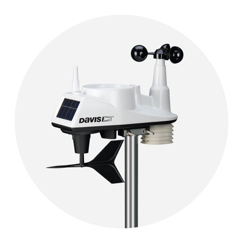
While we have tested the Wireless Vantage Pro2 radio extensively, each site and each installation presents its own issues and challenges. Obstructions, particularly metallic ones, often cut down your station’s reception distance. Be sure to test reception between the console and ISS, in the locations you intend to install them, before permanently mounting your ISS or other transmitter(s). The legacy console’s reception status displays at the lower right corner of the screen.
- An “X” flashes for every data packet received by the console.
- An “R” displays when the console is trying to re-establish a lost connection. The console tries for 10 minutes to re-establish a connection before going into L Mode.When no data packets have been received for 10 minutes, the console dashes-out any missing sensor readings.
- An “L” displays when the signal is lost (and the console is “asleep.”) The console stays in this mode for 15 minutes until returned to “R” mode. To force the console into “R” mode (“wake up” the console), enter and exit Setup Mode.
For more details on your console reception, Console diagnostic mode
Installation
The standards for siting a station are to have temperature sensors 4 to 6 feet (1.2 to 2.0 meters) above the surface, and 30 feet (9.1 meters) for wind.


But there is more to consider than just height. An anemometer at 33 feet (10.1 meters) in the narrow alley between two 100-foot (30.5-meter) buildings and a temp sensor exactly 5 feet (1.5 meters) above a large black asphalt parking lot will not give you very usable data. But, what if what you want to know is how hot it gets in the parking lot, or how fast the wind whistles down that urban canyon? The point is, you want data that pertains to your specific needs and environment.
Siting standards are guidelines that most users probably can't meet perfectly. You want to mount your weather station as close to the standards as possible, but odds are, you won't be able to find the perfect site.
For those who require more precise siting, a Vantage Pro2 is the station for you, because the anemometer can be mounted on the roof or a tower, and the rest of the sensors at 6 feet (1.8 meters).
In the case of Vantage Vue, the two sensors cannot be separated, so they must be mounted at the same height. A compromise would work, but perhaps a better way to look at it would be to consider which information is most important to you. If you live where wind is the most interesting weather variable and you have many trees sheltering your yard, mounting on the roof, 6 feet (1.8 meters) above the surface, will be the best option. (But bear in mind that you will need to access your station for routine maintenance.) If you really are more interested in rain and temp, then finding a spot where the station can be mounted at 5 to 6 feet (1.5 to 1.8 meters) will give you accurate readings for temp and rain and will allow easy maintenance. (Bear in mind that wind readings will be affected by obstructions on the ground.)
For more information about finding an installation location, see Application Note 30: Reporting Quality Observations to NOAA and other weather observation groups.
If the anemometer arm cannot be mounted pointing to true north, use this procedure to correct the wind direction console reading.
- Check the current direction of the wind vane on the anemometer. Compare it to the wind direction reading on the legacy console.
- Press WIND as necessary to display the wind direction in degrees.
- Press and release 2ND, then press and hold SET.
- The wind direction variable will begin to blink.
- Continue holding the key until the CAL message appears in the ticker. The ticker displays the current wind direction calibration value.
- Press the < and > keys to select digits in the anemometer’s current reading.
- Press the + and - keys to add/subtract from the anemometer reading.
- Repeat steps 6 and 7 until you have entered the offset value from Step 1.
- Press DONE to exit calibration.
Electrical
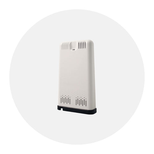
I do not want to replace may batteries, can I power the outside portion (ISS) of the Vantage Pro 2 some other way?
Yes, you can purchase a power supply (same model as used for the console - 6625)
You would unplug the solar and remove the battery. Then plug the power adapter into port 2 below.(Note, it will appear to seat only partially, this is actually fully seated)

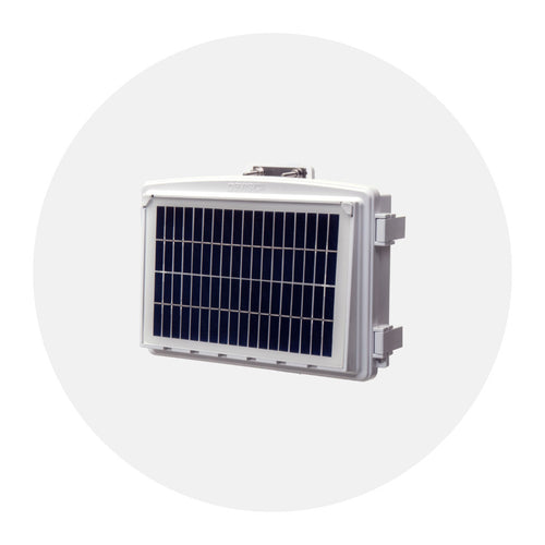
We've put together some ways you can use our shelters and solar power kits:
Use a Solar Power Kit, shelter, or extra solar panel for your Vantage Pro2 or Vantage Vue console, Weather Envoy8X, or Weather Envoy. View various installation options for each product. (6612, 6614, 6616, 6618)
Click for installation diagrams.
To power down your console:
- If it is powered using a cable, unplug the cable.
- If the console has batteries, remove the batteries.
That's it! The console is shut off completely.
The Vantage Vue or Vantage Pro 2 consoles can use 2 different sources of power. They can use AC power from the wall or it can use batteries as the primary power. If you are not using AC power and are using batteries ONLY, the console batteries will typically last about 9 months.
However, if you are using a WeatherLink IP (6555) or a cabled console, the batteries are ONLY good for BACKUP power. If you have a console with a WeatherLink IP (6555), the batteries will last 2 days. Using a cabled console the batteries will last 27 days.

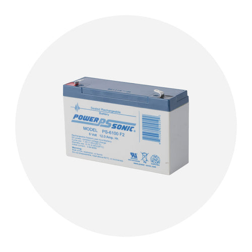
The wireless Vantage Pro2 uses a CR-123A 3-volt lithium battery to back up the capacitor. When the battery is low the console will display a "Low battery on station 1" error message. It will need to be replaced every few years (8 months without sunlight- greater than 2 years depending on solar charging)

Note: Once triggered, a low battery warning does not reset automatically until midnight. So even if you’ve inserted a brand new battery, the warning may not disappear until the next day – this is perfectly normal.


Display
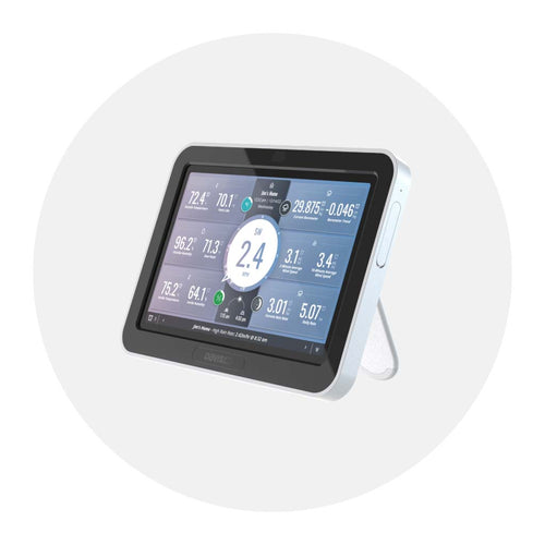
In addition to logging weather data, the Vantage Pro2 legacy console (6312, 6312C) continuously monitors the station’s radio reception. You may find this information very helpful, especially when you are choosing locations for your console and ISS. The Console Diagnostics Mode consists of two screens, the Statistical Diagnostic Screen and the Reception Diagnostic Screen. The Statistical Diagnostic screen applies for both cabled and wireless weather stations. The Reception Diagnostic screen applies only to wireless weather stations and is not accessible to a cabled weather station.
Note: Radio transmission data used by the diagnostic screens clears each day at midnight.
Diagnostic Screen Commands • Press and hold TEMP, then press HUM to display the Statistical Diagnostic screen.
- Press the > key to display signal statistics for the next installed transmitter ID.
- Press 2ND and then press CHILL to toggle between the Statistical and Reception Diagnostic screens.
- A degree (°) sign displays in right corner of value 1 of the Reception Diagnostic screen (screen 2) to differentiate which screen is currently displayed.
- Press DONE to exit the diagnostic screen.
Screen 1: Statistical Diagnostic Screen
The Statistical Diagnostic displays information about how data is being received from the weather station to the console. The information that is displayed in this screen includes:

Note: All values with a * mark the value as being for Davis Instruments Internal use. All values with a ‡ mark values that are the same on both the Statistical and Reception Diagnostic screens.
- Time of day or number of times the anemometer switch was seen closed*.The switch closes once each revolution of the anemometer wind cups. Press WIND to toggle between these two values.
- Date or the number of times the anemometer switch was seen open*. Press WIND to toggle between these two values.
- Number of packets containing CRC errors received. The system runs a CRC check on data packets. Any data packets that don’t pass this check are considered to contain errors and are discarded. These are considered bad packets.
- The total number of bad data packets including missed packets and CRC errors. Missed packets are described as when a data packet is expected, but is not recognized as a data packet by the console.
- Percentage of good packets received.
- Total number of good packets received.
- Number of times the console resynchronized with the transmitter. The console will attempt to resynchronize with the station after 20 consecutive bad packets.
- Maximum number of bad packets in a row without resynchronization.
- Current streak of consecutive bad packets. The counter increments when the console is synchronized but the packet is bad. This value is reset to zero when a good packet is received.
- Longest streak of consecutive good packets received.
- Current streak of consecutive good packets received.
- Graph of the daily percentage of good data packets received over the last 24 days.
- Background noise level. This refers to the undesirable signal level the console hears while it is in the process of acquiring a signal from a station. The range displayed is from 5 to 60. When the noise level is high, try to move the console closer to the station to get a stronger signal. Small background noise level does not always guarantee good reception. The signal strength between the station and the console needs to be stronger than the background noise level in order for the console to receive clearly. If there are reception problems while a small background noise level is still being displayed, make sure the console is within reasonable range of the station. If the console currently has acquired all the station signals it is set to receive, the background noise level displayed is the last noise level measurement taken before acquisition finished.
- Current console battery voltage. Ignore this value if using the AC Adapter only to power the console.
- Repeater ID currently communicating with the console. If a repeater or group of repeaters is used to relay station information to the console, the Repeater ID displayed is the repeater that the console is set to receive. If the console is not listening to repeaters, this section remains blank. Please see Application Note 25 available on the Davis Instruments Support web page for more information on using repeaters.
- The console’s reception status. See “Troubleshooting Reception Problems” on page 38 for information on the status types.
Screen 2: Reception Diagnostic Screen
The Reception Diagnostic screen displays information pertinent to the console’s wireless reception. To view this screen from the Statistical Diagnostic screen, press 2ND and then press CHILL. The degree sign displaying in the upper left corner next to value 1 verifies that the Reception Diagnostic screen is currently displayed.
The information that is displayed in this screen includes:

- 8-bit timer value of next reception.*
- Radio frequency error of the last packet received successfully. In normal operation, this value is +1, -1, or 0. This value affects the value of #5 on the next page.
- Percentage of good data packets.‡
- Signal strength of the last packet received. The values displayed in this field should generally be between 20 and 60. If a packet is not received successfully, the signal strength field is dashed out (--).
- Current frequency correction factor. Shows the Automatic Frequency Control setting.
- Frequency index of the next packet to be received.*
- Current number of consecutive bad packets.‡
- The number of times that the Phase Lock Loop did not lock.*
- Current streak of consecutive good packets received.‡
If your console gives a set of three beeps over and over again, you may have inadvertently set an alarm. Follow these steps on the console to clear alarms.
- Press ALARM to enter alarm mode. The ALARM and HIGHS icons appear.
- Select the alarm setting you wish to clear.
- Press 2ND, then press and hold CLEAR until the setting changes to all dashes. You have cleared the alarm setting.
- Press DONE to exit Alarm Mode.
These steps will clear the any High alarms that have been set. To clear any Low alarms, follow the steps below.
- Press ALARM to enter alarm mode.
- Press the High/Low button to display low alarms.
- Select the alarm setting you wish to clear.
- Press 2ND, then press and hold CLEAR until the setting change to all dashes. You have cleared the alarm setting.
- Press DONE to exit Alarm Mode.
Note: To clear all alarms, enter Alarm mode (press and release the ALARM key), then press and hold the ALARM key until all the fields become dashed.
When your console starts, it's normal for it to go into the "Receiving from" mode. This mode helps determine if there are other stations in your area and what station they are set to. To bypass the "Receiving from" mode, press and hold the "Done" button for two seconds.
Data
You can calibrate inside & outside temperature, inside & outside humidity, as well as any extra temperature/humidity sensor readings you have transmitting to your Vantage Pro2.
- Select a variable to be calibrated.
- Press and release 2ND, then press and hold SET. After a moment, the variable you’ve selected begins to blink. Keep holding SET until the Calibration Offset message displays in the ticker. The ticker displays the current calibration offset.
- Press the+ and - keys to add or subtract from the temperature offset value. Inside and outside temperature are calibrated in 0.1° F or 0.1° C increments, up to a maximum offset of +12.7 (°F or °C) and a minimum offset of -12.8 (°F or °C). The variable will change value and the ticker will show the offset you’ve entered.
- Press DONE to exit calibration.
Mechanical
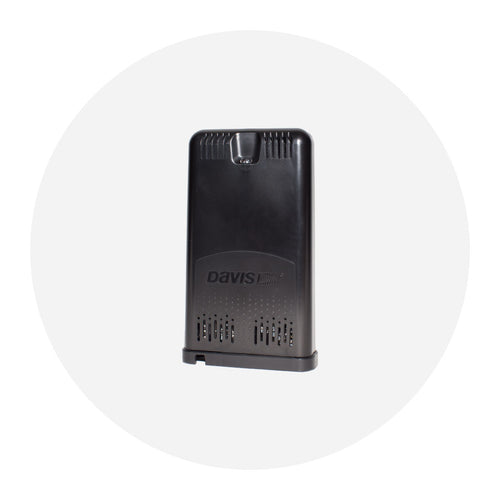
You have to lift up the white plastic piece that is wedged behind the transmitter box. Click the link below and fast forward the video to about 2:00 to see it done.
Environmental
Yes. Freezing temperatures do not damage the rain collector. However, the rain collector will not correctly read the volume of water contained in snow. You can put a cover over the rain collector to keep the snow and ice out during the winter season. Or, you can purchase a Davis heater for the older version of the aerocone to melt freezing precipitation.